
The goal for 2024 was to design a composite throttle pedal to be used in our car that would improve or resolve the weak areas from the previous year’s design. Some of the design considerations included pedal geometry and materials, without undergoing a full re-design process.
Criteria:
Some of the criteria for the throttle pedal design this year included improving the areas that failed and reducing weak points from last year. This project was not intended to be a full redesign. We wanted to keep a similar geometry for the face and use the same dimensions from last year. The reason for this is from driver feedback and satisfaction with the current design. I wanted to increase the stability of the connection points including those between the arm and face. The pedal also needed to be able to integrate with the pedal box connections including the pivot, bearings, throttle cable, throttle stop, and any other mechanisms provided by controls. Finally, we have chosen to design for more force than the expected maximum loading to prevent failures from varied loading.
Concepts:
The main differences in the concepts considered from the throttle pedal stemmed from geometry variations. Using the same dimensions as last year, I was limited to exploring curved vs flat faces and tapered vs straight angle attachments between the pedal face and arm. I was also able to vary the layers of carbon fibre and the type for the layup schedule.
Last Year’s Pedal
Areas to improve:
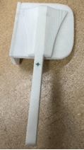
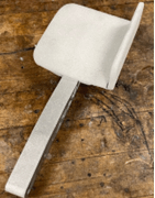
The previous composite throttle pedal had been made of two sperate pieces for the arm and the flag and they were epoxied together after curing. This is one of the areas that experienced failure in addition to some delamination that occurred on the pedal arm. Although, it was not critical as it was able to be repaired with a wet layup. However, this was still undesirable and one of the areas I wanted to focus on improving with this year’s pedal.
The First Iteration
Coming up with designs:
I knew that I wanted to improve the stability of the connection between the pedal arm and face. Last year’s pedal was made with a separate carbon fibre arm and face that were epoxied together. There was a failure where the face and arm separated and had to be put back together with a wet layup. To minimize the chance of that failure re-occurring, I explored designs that had the pedal arm and face in the layup together. I also looked at tapered arm geometries to help reduce stress concentrations in the carbon fiber.

Manufacturing:
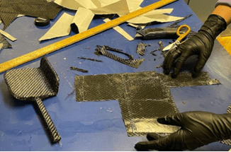
A prototype composite throttle was designed in CAD based on the concepts I explored. The core was a CNC cut rohacell foam arm piece, pedal face, and flag for a total of three pieces. 3 layers of twill weave carbon fiber were done in a 0/90-degree layup schedule around the foam core, and it was oven cured with vacuum bagging for debulking. Beam bending calculations were done in excel to come up with a starting point of three layers of carbon on all faces. An aluminum bracket was made by bending sheet metal and belt sanding one end to round the edges. It was epoxied onto the pedal arm after curing.
Testing:
We designed a jig to proof load the prototype throttle pedal until failure. Holes were drilled in the aluminum bracket for mock attachment pieces to mimic the force loading effects of the pivot point and throttle stop mechanisms. A testing jig was made to load the pedal arm and find the maximum tensile or compressive strength and the failure loading. We used hanging masses to simulate the loads of the driver’s foot pressing on the pedal.
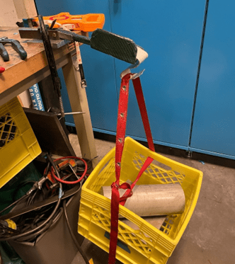
Billet was added in increments to the testing jig up until failure occurred at 40 lbs (~178N). The pedal arm failed at the interface between the carbon fiber pedal face and the arm. This was expected as there would be force concentrations at the 90-degree bend at the face, as well as the highest point of the bending moment in the arm. However, we were not satisfied with the result of the proof loading as the pedal was able to hold significantly less load than we were designing for. To help overcome this we decided that we would need to add additional layers of carbon fiber to the next iteration to improve the strength.
The second iteration
Updated Composite Pedal:
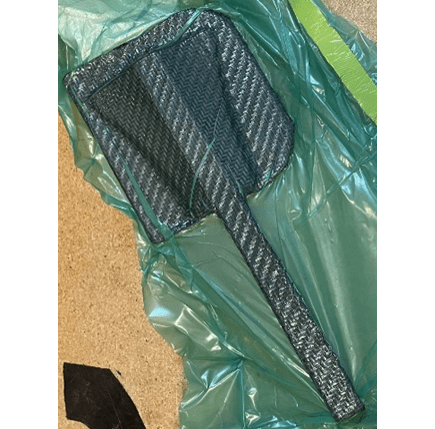
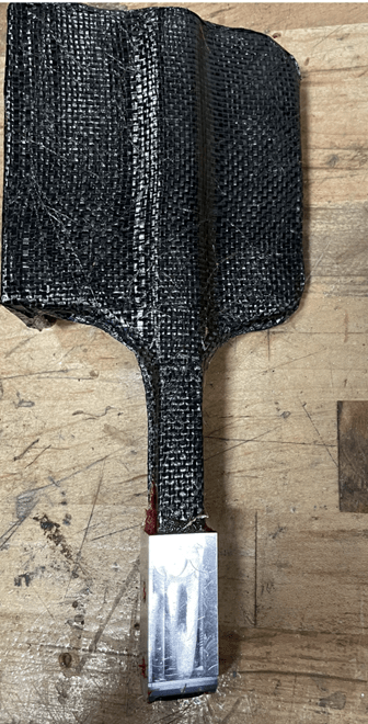
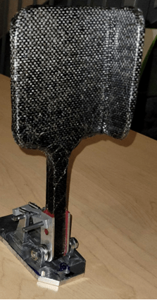
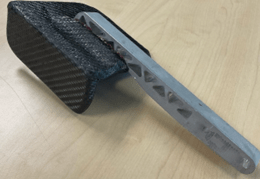
Based on the failure during the proof loading of the prototype, I decided to make the arm and face one piece of foam instead of two. This made the face flush with the pedal arm and completely remove the 90-degree angle responsible for the stress concentration. As a result, the overall pedal face and arm is approximately 1/3 inch thinner. I also added a taper between the face and arm to further reduce force concentrations where it broke during proof loading and additional fillets around the arm and rear face connection. The flag size was kept the same. Instead of making the aluminum bracket out of bent sheet metal I used a CNC machined aluminum bracket that was co-cured with 2 layers of film adhesive between pedal arm and Aluma-prepped bracket. The same cure cycle was used as the prototype, also with a vacuum bag for debulking.

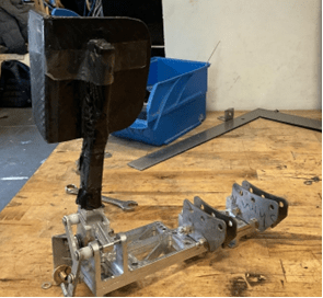
The Back-up Aluminum Pedal
For risk management reasons we decided to make a backup pedal with an aluminum arm in case the composite one ended up breaking at a test day or during the competition. The face of the prototype was in good condition, so a slot was cut into it to epoxy in the aluminum arm. This was done to save time and materials instead of making an entirely new face. This pedal was not intended to ever be used, but due to an unfortunate failure of the composite pedal during pedal box assembly, it was used for one of our test days.
We were unsure of the exact reason for the composite pedal failure as it was not being loaded as expected when it broke. The pedal base was being wrench tightened and a team member was using the pedal arm to brace the wrench when tightening. We suspected that the pedal either failed in fatigue because it broke on the rear side (compression face) or from the compression applied unexpectedly by the wrench.
To prevent further failures due to our uncertainty around the composite pedal breaking, we decided to change the design to an aluminum arm and composite face. While this means that we did not meet our goal of successfully designing and using a composite throttle pedal and arm, we felt that it would be the safest option in the amount of time remaining before competition.
The Final Pedal Iteration
Final Design Adjustments:
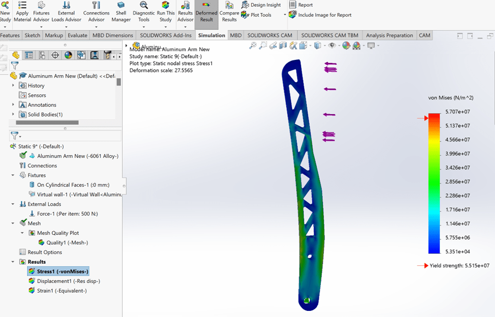
I designed an aluminum throttle pedal arm in SolidWorks using FEA and inspiration from the brake pedal arm to come up with the shape. I figured out the required width of the arm by completing iterative loading simulations as the maximum width is constrained by the throttle stop. I then made triangle cut outs to help reduce the weight and added tapers between the thicker parts at the force concentrations by using fillets and chamfers.
Manufacturing:
The pedal arm was water jet cut out of 6061 aluminum billet. The composite pedal face was a rohacell foam core with 3 layers of 0/90-degree layup schedule twill carbon fibre. I added tapered slots on the back face to constrain the pedal arm and ensure that it was aligned correctly during the co-cure. The arm and face were co-cured with 2 layers film adhesive between them, and the arm was Aluma-prepped. The pedal was vacuum bagged, and oven cured at the same cure cycle.

The final pedal interfaced successfully with pedal box and ran at test day without any issues. Currently we are keeping the other aluminum pedal as a backup as it also ran successfully during a test day. While we were not able to run a fully composite throttle pedal this year, we are confident in our decision to return to an aluminum arm. There was not enough time to appropriately test and determine the exact causes of the failure of the composite pedal intended to run this year, but this is something that would be explore further after competition.

